An electrical switch is any device used to interrupt the flow of electrons in a circuit. Switches
are essentially binary devices: they are either completely on ("closed") or completely or ("open").
There are many different types of switches, and we will explore some of these types in this chapter.
Though it may seem strange to cover this elementary electrical topic at such a late stage in this
book series, I do so because the chapters that follow explore an older realm of digital technology based
on mechanical switch contacts rather than solid-state gate circuits, and a thorough understanding of
switch types is necessary for the undertaking. Learning the function of switch-based circuits at the
same time that you learn about solid-state logic gates makes both topics easier to grasp, and sets
the stage for an enhanced learning experience in Boolean algebra, the mathematics behind digital
logic circuits.
The simplest type of switch is one where two electrical conductors are brought in contact with
each other by the motion of an actuating mechanism. Other switches are more complex, containing
electronic circuits able to turn on or off depending on some physical stimulus (such as light or
magnetic field) sensed. In any case, the final output of any switch will be (at least) a pair of
wire-connection terminals that will either be connected together by the switch's internal contact
mechanism ("closed"), or not connected together ("open").

Any switch designed to be operated by a person is generally called a hand switch, and they are
manufactured in several varieties:
Toggle switch
Toggle switches are actuated by a lever angled in one of two or more positions. The common
light switch used in household wiring is an example of a toggle switch. Most toggle switches will
come to rest in any of their lever positions, while others have an internal spring mechanism returning
the lever to a certain normal position, allowing for what is called "momentary" operation.
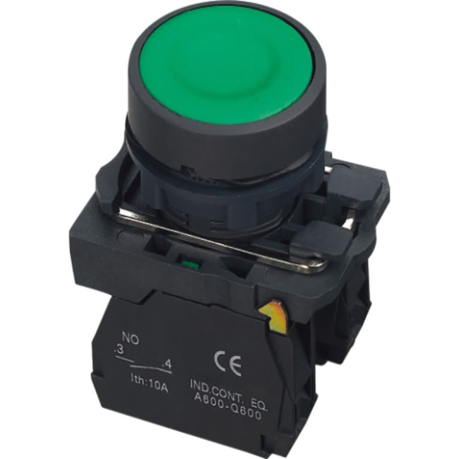
Push button switch
Push button switches are two-position devices actuated with a button that is pressed and released.
Most push button switches have an internal spring mechanism returning the button to its "out," or
"unpressed," position, for momentary operation. Some push button switches will latch alternately on
or off with every push of the button. Other push button switches will stay in their "in," or "pressed,"
position until the button is pulled back out. This last type of push button switches usually have a
mushroom-shaped button for easy push-pull action.

are essentially binary devices: they are either completely on ("closed") or completely or ("open").
There are many different types of switches, and we will explore some of these types in this chapter.
Though it may seem strange to cover this elementary electrical topic at such a late stage in this
book series, I do so because the chapters that follow explore an older realm of digital technology based
on mechanical switch contacts rather than solid-state gate circuits, and a thorough understanding of
switch types is necessary for the undertaking. Learning the function of switch-based circuits at the
same time that you learn about solid-state logic gates makes both topics easier to grasp, and sets
the stage for an enhanced learning experience in Boolean algebra, the mathematics behind digital
logic circuits.
The simplest type of switch is one where two electrical conductors are brought in contact with
each other by the motion of an actuating mechanism. Other switches are more complex, containing
electronic circuits able to turn on or off depending on some physical stimulus (such as light or
magnetic field) sensed. In any case, the final output of any switch will be (at least) a pair of
wire-connection terminals that will either be connected together by the switch's internal contact
mechanism ("closed"), or not connected together ("open").

manufactured in several varieties:
Toggle switch
Toggle switches are actuated by a lever angled in one of two or more positions. The common
light switch used in household wiring is an example of a toggle switch. Most toggle switches will
come to rest in any of their lever positions, while others have an internal spring mechanism returning
the lever to a certain normal position, allowing for what is called "momentary" operation.
Push button switch
Push button switches are two-position devices actuated with a button that is pressed and released.
Most push button switches have an internal spring mechanism returning the button to its "out," or
"unpressed," position, for momentary operation. Some push button switches will latch alternately on
or off with every push of the button. Other push button switches will stay in their "in," or "pressed,"
position until the button is pulled back out. This last type of push button switches usually have a
mushroom-shaped button for easy push-pull action.