Electric motors rely on principles of magnetism. A coil of wire carrying a current in a magnetic field experiences a force that tends to make it rotate. This effect can be used to make an electric motor. Most often, copper windings are powered by an electric current, generating a magnetic field. This interacts with a separate magnetic field – often created by an array of permanent magnets. The interaction between the two fields causes the rotor to turn.
Wednesday, June 21, 2023
Electrical motors construction
Electric motors are used in many applications and industries. They are used in electric cars, elevators, fans, pumps, and many other devices. The construction of an electric motor can be done using the rotor, bearings, stator, air gap, windings, commutator, etc. The rotor is the moving part of the motor and its main function is to rotate the shaft for generating mechanical power. The stator is the fixed part of the motor and it consists of laminations of silicon steel. The stator has two electrical components: magnets set and an armature. One of them is attached to the stator and the other to the rotor, together making a magnetic circuit.

Electrical motors
Electrical motors convert electrical energy into mechanical energy by using electromagnetic phenomena. They are used in a wide range of applications such as electric vehicles, industrial machinery, household appliances, and more.
There are several types of electric motors such as AC motors, DC motors, stepper motors, and more. Each type has its own advantages and disadvantages depending on the application.
Electric motors convert electrical energy to rotational mechanical energy by using electromagnets with currents to create force. The basic principle underlying the functioning of an electrical motor is Faraday’s Law of induction, which states that a force is created when an alternating current interacts with a changing magnetic field¹.
There are mainly three types of electric motor: DC Motor, Induction Motor, and Synchronous Motor. All of these motors work with more or less the same principle, which depends upon the interaction of magnetic field with current¹.
Friday, June 9, 2023
electrical voltage
Electric potential difference, also known as voltage, is the external work needed to bring a charge from one location to another location in an electric field. Electric potential difference is the change of potential energy experienced by a test charge that has a value of.
Medium voltage is a class of nominal system voltages that is higher than 1,000 V and lower than 100 kV. It is commonly used for subtransmission, primary distribution, and industrial motors. The range of medium voltage may vary from 600 V to 69 kV depending on the equipment ratings and standards.
An increasing amount of low carbon technologies (LCT) such as solar photovoltaic, wind turbines and electric vehicles are being connected at medium and low voltage levels to electric power networks.
Monday, May 29, 2023
electrical current
Electric current is the movement of electric charge carriers such as electrons having negative charge, protons having positive charge, ions (atoms that have lost or gained one or more electrons), or holes (electron deficiencies that may be thought of as positive particles) ². The intensity of electric current is usually measured in amperes.
Electric current is used in many practical applications such as charging batteries, operating household appliances like bread toasters, baking ovens, televisions and mobile phones¹. It also plays an important role in industries, transportation and communication.
Tuesday, May 23, 2023
electrical switchboards
An electrical switchboard is a piece of equipment that distributes electric power from one or more sources of supply to several smaller load circuits. It is an assembly of one or more panels, each of which contains switching devices for the protection and control of circuits fed from the switchboard².
Switchboards are used to safely distribute electricity throughout commercial and industrial facilities. A switchboard is a component of an electrical distribution system which divides an electrical power feed into branch circuits while providing a protective circuit breaker or fuse for each circuit in a common enclosure

Thursday, November 26, 2015
calculate online an equivalent two sires capacitors
Easy way to calculate an equivalent two sires capacitors:
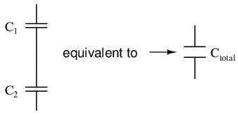
I want results in
result
Friday, November 13, 2015
Electrical google Search Engine
ElectricalGoogle Search Engine helps you to search in an electrical and automatic control web sites, so all of the results will be related to your study material as an Engineer, If you are an engineer stop wasting your time ang use ElectricalGoogle.
Saturday, November 7, 2015
Online Electrical Power Calculation
Easy way to calculate an AC and DC electrical active power in kilo watt:
result
Thursday, June 25, 2015
AC Motors 2
Introduction to motors cont.:
An object in motion travels a distance in a given time. Speed is the ratio of the distance traveled and the time it takes to travel the distance.
The linear speed of an object is a measure of how long it takes the object to get from point A to point B. Linear speed is usually given in a form such as meters per second (m/s).
The angular speed of a rotating object is a measurement of how long it takes a given point on the object to make one complete revolution from its starting point. Angular speed is generally given in revolutions per minute (RPM).
An object can change speed. An increase in speed is called acceleration. Acceleration occurs only when there is a change in the force acting upon the object. An object can also change from a higher to a lower speed. This is known as deceleration (negative acceleration).
Mechanical systems are subject to the law of inertia. The law of inertia states that an object will tend to remain in its current state of rest or motion unless acted upon by an external force. This property of resistance to acceleration/deceleration is referred to as the moment of inertia. The English system of measurement is pound-feet squared (lb-ft2).
If we look at a continuous roll of paper, for example, we know that when the roll is stopped it would take a certain amount of force to overcome the inertia of the roll to get it rolling. The force required to overcome this inertia can come from a source of energy such as a motor. Once rolling, the paper will continue unwinding until another force acts on it to bring it to a stop.
An object in motion travels a distance in a given time. Speed is the ratio of the distance traveled and the time it takes to travel the distance.
The linear speed of an object is a measure of how long it takes the object to get from point A to point B. Linear speed is usually given in a form such as meters per second (m/s).
The angular speed of a rotating object is a measurement of how long it takes a given point on the object to make one complete revolution from its starting point. Angular speed is generally given in revolutions per minute (RPM).
An object can change speed. An increase in speed is called acceleration. Acceleration occurs only when there is a change in the force acting upon the object. An object can also change from a higher to a lower speed. This is known as deceleration (negative acceleration).
Mechanical systems are subject to the law of inertia. The law of inertia states that an object will tend to remain in its current state of rest or motion unless acted upon by an external force. This property of resistance to acceleration/deceleration is referred to as the moment of inertia. The English system of measurement is pound-feet squared (lb-ft2).
If we look at a continuous roll of paper, for example, we know that when the roll is stopped it would take a certain amount of force to overcome the inertia of the roll to get it rolling. The force required to overcome this inertia can come from a source of energy such as a motor. Once rolling, the paper will continue unwinding until another force acts on it to bring it to a stop.
Wednesday, June 24, 2015
AC Motors 1
AC motors are used worldwide in many residential, commercial, industrial, and utility applications. Motors transform electrical energy into mechanical energy. An AC motor may be part of a pump or fan, or connected to some other form of mechanical equipment such as a winder, conveyor, or mixer. AC motors are found on a variety of applications from those that require a single motor to applications requiring several motors.
Before discussing AC motors it is necessary to understand some of the basic terminology associated with motor operation. Many of these terms are familiar to us in some other context. Later in the course we will see how these terms apply to AC motors.
In simple terms, a force is a push or a pull. Force may be caused by electromagnetism, gravity, or a combination of physical means.
Net force is the vector sum of all forces that act on an object, including friction and gravity. When forces are applied in the same direction they are added. For example, if two 10 pound forces were applied in the same direction the net force would be 20 pounds.
If 10 pounds of force were applied in one direction and 20 pounds of force applied in the opposite direction, the net force would be 10 pounds and the object would move in the direction of the greater force.
If 10 pounds of force were applied equally in both directions, the net force would be zero and the object would not move.
Torque is a twisting or turning force that causes an object to rotate. For example, a force applied to the end of a lever causes a turning effect or torque at the pivot point. Torque (τ) is the product of force and radius (lever distance).
τ = Force x Radius
In the English system torque is measured in pound-feet (lb-ft) or pound-inches (lb-in).If 10 lbs of force were applied to a lever 1 foot long, for example, there would be 10 lb-ft of torque.
An increase in force or radius would result in a corresponding increase in torque. Increasing the radius to two feet, for example, results in 20 lb-ft of torque.
Before discussing AC motors it is necessary to understand some of the basic terminology associated with motor operation. Many of these terms are familiar to us in some other context. Later in the course we will see how these terms apply to AC motors.
In simple terms, a force is a push or a pull. Force may be caused by electromagnetism, gravity, or a combination of physical means.
Net force is the vector sum of all forces that act on an object, including friction and gravity. When forces are applied in the same direction they are added. For example, if two 10 pound forces were applied in the same direction the net force would be 20 pounds.
If 10 pounds of force were applied in one direction and 20 pounds of force applied in the opposite direction, the net force would be 10 pounds and the object would move in the direction of the greater force.
If 10 pounds of force were applied equally in both directions, the net force would be zero and the object would not move.
Torque is a twisting or turning force that causes an object to rotate. For example, a force applied to the end of a lever causes a turning effect or torque at the pivot point. Torque (τ) is the product of force and radius (lever distance).
τ = Force x Radius
In the English system torque is measured in pound-feet (lb-ft) or pound-inches (lb-in).If 10 lbs of force were applied to a lever 1 foot long, for example, there would be 10 lb-ft of torque.
An increase in force or radius would result in a corresponding increase in torque. Increasing the radius to two feet, for example, results in 20 lb-ft of torque.
Wednesday, June 17, 2015
Circuit Breakers Types
Instantaneous magnetic-trip-only circuit breakers do not provide overload protection and are used on motor circuits where overload protection is provided by a motor starter. The current level at which an instantaneous trip circuit breaker trips is adjustable. The name comes from the electromagnet used to sense short circuit current. The purpose of overload protection is to prevent the motor from operating beyond its full-load capability. In the schematic illustrated below, a motor is supplied through a 3-pole circuit breaker, motor starter contacts and separately supplied overload contacts. Heat generated from excessive current will cause the overload contacts to open, removing power from the motor.

Thermal-magnetic circuit breakers have both overload and instantaneous trip features. When an overload condition exists, the excess current will generate heat, which is detected in the circuit breaker. After a short period of time, dependent on the rating of the breaker and amount of overload, the breaker will trip, disconnecting the load from the voltage source. If a short circuit occurs, the breaker responds instantaneously to the fault current and disconnects the circuit.
The user does not have access to the trip unit on some circuit breakers. This means the trip unit cannot be changed with another. Interchangeable trip is actually a design feature that is available on some thermal-magnetic and some solid state breakers. The advantage of a breaker with an interchangeable trip unit is the user can change the continuous current rating of the breaker without replacing the breaker. This is done by replacing the trip unit with one of a different rating.
molded case circuit breakers are available as a molded case switch. Molded case switches employ the same operating mechanism as the thermal magnetic and magnetic only units. A preset instantaneous function is factory installed to allow the switch to trip and protect itself at a high fault current, but the switch provides no thermal overload protection.
Many electrical distribution systems can deliver large short circuit currents to electrical equipment. This high current can cause extensive damage. Current limiting circuit breakers will reduce the current flowing in the faulted circuit to substantially less magnitude. This helps protect expensive equipment. One way to accomplish current limiting is with an additional set of contacts that feature two moveable arms. These are referred to as dual-pivot contacts, which separate even more quickly than the single-pivot contacts. The dual-pivot contacts are connected in series with the single-pivot contacts. As with the single-pivot design, current flows in opposite directions through the contact arms, creating a magnetic repulsion. As current increases, the magnetic repulsion force increases.
In an overload condition where current may only be one to six times normal current, the contacts remain closed until the breaker trips. In a short circuit condition fault current is extremely high, both sets of contact arms may open simultaneously, generating high impedance arcs. The contact gap of the dual-pivot contacts increases more rapidly, therefore generating arc impedance more rapidly. Once the arcs are extinguished, the dual-pivot contacts close on their own due to spring tension. The single-pivot contacts are held open by the breaker mechanism, which will have tripped during the fault and must be manually reset.
Solid state circuit breakers function similarly to thermal-magnetic breakers. The basic breaker mechanism is still mechanical. The tripping unit is solid state. As with the thermal-magnetic tripping unit, the Sensitrip circuit breaker tripping unit performs the following three functions:
Senses magnitude of current flow,Determines when current becomes excessive,Determines when to send a trip signal to the breaker.
Mechanism of these circuit breakers use a microprocessor to execute numerous functions programmed in the unit. These units have a greater degree of accuracy and repeatability. Adjustments on the trip unit allow the user to select numerical values the microprocessor will use in performing protective functions. Current sensors mounted in the trip unit monitor the value of load current. The value of current is reduced to a low level and converted to a digital voltage, which is used by the microprocessor. The microprocessor continuously compares the line current with the value set by the user. When current exceeds a preset value for the selected time, the trip unit sends a signal to a magnetic latch. The magnetic latch opens the breaker’s contacts, disconnecting the protected circuit from the power source.
Thermal-magnetic circuit breakers have both overload and instantaneous trip features. When an overload condition exists, the excess current will generate heat, which is detected in the circuit breaker. After a short period of time, dependent on the rating of the breaker and amount of overload, the breaker will trip, disconnecting the load from the voltage source. If a short circuit occurs, the breaker responds instantaneously to the fault current and disconnects the circuit.
The user does not have access to the trip unit on some circuit breakers. This means the trip unit cannot be changed with another. Interchangeable trip is actually a design feature that is available on some thermal-magnetic and some solid state breakers. The advantage of a breaker with an interchangeable trip unit is the user can change the continuous current rating of the breaker without replacing the breaker. This is done by replacing the trip unit with one of a different rating.
molded case circuit breakers are available as a molded case switch. Molded case switches employ the same operating mechanism as the thermal magnetic and magnetic only units. A preset instantaneous function is factory installed to allow the switch to trip and protect itself at a high fault current, but the switch provides no thermal overload protection.
Many electrical distribution systems can deliver large short circuit currents to electrical equipment. This high current can cause extensive damage. Current limiting circuit breakers will reduce the current flowing in the faulted circuit to substantially less magnitude. This helps protect expensive equipment. One way to accomplish current limiting is with an additional set of contacts that feature two moveable arms. These are referred to as dual-pivot contacts, which separate even more quickly than the single-pivot contacts. The dual-pivot contacts are connected in series with the single-pivot contacts. As with the single-pivot design, current flows in opposite directions through the contact arms, creating a magnetic repulsion. As current increases, the magnetic repulsion force increases.
In an overload condition where current may only be one to six times normal current, the contacts remain closed until the breaker trips. In a short circuit condition fault current is extremely high, both sets of contact arms may open simultaneously, generating high impedance arcs. The contact gap of the dual-pivot contacts increases more rapidly, therefore generating arc impedance more rapidly. Once the arcs are extinguished, the dual-pivot contacts close on their own due to spring tension. The single-pivot contacts are held open by the breaker mechanism, which will have tripped during the fault and must be manually reset.
Solid state circuit breakers function similarly to thermal-magnetic breakers. The basic breaker mechanism is still mechanical. The tripping unit is solid state. As with the thermal-magnetic tripping unit, the Sensitrip circuit breaker tripping unit performs the following three functions:
Senses magnitude of current flow,Determines when current becomes excessive,Determines when to send a trip signal to the breaker.
Mechanism of these circuit breakers use a microprocessor to execute numerous functions programmed in the unit. These units have a greater degree of accuracy and repeatability. Adjustments on the trip unit allow the user to select numerical values the microprocessor will use in performing protective functions. Current sensors mounted in the trip unit monitor the value of load current. The value of current is reduced to a low level and converted to a digital voltage, which is used by the microprocessor. The microprocessor continuously compares the line current with the value set by the user. When current exceeds a preset value for the selected time, the trip unit sends a signal to a magnetic latch. The magnetic latch opens the breaker’s contacts, disconnecting the protected circuit from the power source.
Tuesday, June 16, 2015
Circuit Breaker Design
Circuit breakers are constructed in five major components:
Frame (Molded Case) Contacts, Arc Chute Assembly,Operating Mechanism and Trip Unit.
The frame provides an insulated housing to mount the circuit breaker components. The construction material is usually a thermal set plastic such as glass-polymer. The construction material can be a factor in determining the interruption rating of the circuit breaker. Frame ratings indicate several pieces of important information such as; maximum voltage, ampere rating, interrupting rating, and physical size.
Circuit breakers use contacts to break the circuit and stop the flow of energy. Some conventional circuit breakers use a straight-through contact arrangement. The electrical path through the contacts is a straight line.a magnetic field is developed around a current carrying conductor. The magnetic fields developed around the contact arms of a straight-through contact arrangement have little or no effect on the contacts arms. During a fault, the contacts are only opened by the mechanical operation of the circuit breaker spring.
But current causes heat, which is destructive to electrical equipment. A rise in current causes a corresponding rise in heat. In reality, the thermal energy the circuit will see is proportional to the square of the current multiplied by the time the current flows (I2T). This means that the higher the level of current, the shorter the time it takes for heat to damage equipment. In the following illustration, IP represents the peak level the fault current rises before the breaker contacts open.
The blow-apart contacts are two contact arms are positioned parallel to each other as shown in the following illustration. As current flows through the contact arms, magnetic fields are set up around each arm. Because the current flow in one arm is opposite in direction to the current flow in the other arm, the two magnetic fields oppose each other. The strength of the magnetic field is directly proportional to the amount of current. During normal current conditions, the magnetic field is not strong enough to force the contacts apart.
When a fault develops, current increases which increases the strength of the magnetic field. The increased strength of the opposing magnetic fields actually helps to open the contacts faster by forcing them apart.
As the contacts open a live circuit, current continues to flow for a short time by jumping the air space between the contacts in the form of an arc. When the contacts open far enough the arc is extinguished and the current flow stops.
The arc can cause burning on the contacts. In addition, ionized gases form inside the molded case. If the arc isn’t extinguished quickly the pressure from the ionized gases could cause the molded case to rupture. An arc chute assembly is used to quench the arc. This assembly is made up of several “U” shaped steel plates that surround the contacts. As the arc is developed it is drawn into the arc chute where it is divided into smaller arcs, which are extinguished faster.
An operating handle is provided to manually open and close the contacts. Molded case circuit breakers (MCCBs) are trip free, meaning that they can’t be prevented from tripping by holding or blocking the operating handle in the “ON” position. There are three positions of the operating handle: “ON” (contacts closed), “OFF” (contacts open), and “TRIPPED” (mechanism in tripped position). The circuit breaker is reset after a trip by moving the handle to the “OFF” position and then to the “ON” position.
The operating handle is connected to the moveable contact arm through an operating mechanism. Molded case circuit breakers use an over-center toggle mechanism that is a quickmake and quick-break design. In the following illustration, the operating handle is moved from the “OFF” to the “ON” position. In this process a spring begins to apply tension to the mechanism. When the handle is directly over the center the tension in the spring is strong enough to snap the contacts closed. This means that the speed of the contact closing and opening is independent of how fast the handle is operated.To open the contacts, the operating handle is moved from the “ON” to the “OFF” position. In this process a spring begins to apply tension to the mechanism. When the handle is directly over the center the tension in the spring is strong enough to snap the contacts open. As in closing the circuit breaker contacts, contact opening speed is independent of how fast the handle is operated.
The trip unit is the “brain” of the circuit breaker. It consists of components that will automatically trip the circuit breaker when it senses an overload or short circuit. The tripper bar is moved by a manual “PUSH TO TRIP” button, a thermal overcurrent sensing element or an electromagnet.
A trip mechanism is held in place by the tripper bar. As long as the tripper bar holds the trip mechanism, the mechanism remains firmly locked in place.The operating mechanism is held in “ON” position by the trip mechanism. When a trip is activated, the trip mechanism releases the operating mechanism, which opens the contacts.
MCCBs, heavy duty and above, can be manually tripped by depressing the red “PUSH TO TRIP” button on the face of the circuit breaker. When the button is pressed the tripper bar rotates up and to the right. This allows the trip mechanism to “unlock” releasing the operating mechanism. The operating mechanism opens the contacts. The “PUSH TO TRIP” button also serves as a safety device by not allowing access to the circuit breaker interior in the “ON” position. If an attempt is made to remove the circuit breaker cover while the contacts are in the closed (“ON”) position, a spring located under the pushbutton will cause the button to lift up. This action will also trip the breaker.
Frame (Molded Case) Contacts, Arc Chute Assembly,Operating Mechanism and Trip Unit.
The frame provides an insulated housing to mount the circuit breaker components. The construction material is usually a thermal set plastic such as glass-polymer. The construction material can be a factor in determining the interruption rating of the circuit breaker. Frame ratings indicate several pieces of important information such as; maximum voltage, ampere rating, interrupting rating, and physical size.
But current causes heat, which is destructive to electrical equipment. A rise in current causes a corresponding rise in heat. In reality, the thermal energy the circuit will see is proportional to the square of the current multiplied by the time the current flows (I2T). This means that the higher the level of current, the shorter the time it takes for heat to damage equipment. In the following illustration, IP represents the peak level the fault current rises before the breaker contacts open.
The blow-apart contacts are two contact arms are positioned parallel to each other as shown in the following illustration. As current flows through the contact arms, magnetic fields are set up around each arm. Because the current flow in one arm is opposite in direction to the current flow in the other arm, the two magnetic fields oppose each other. The strength of the magnetic field is directly proportional to the amount of current. During normal current conditions, the magnetic field is not strong enough to force the contacts apart.
When a fault develops, current increases which increases the strength of the magnetic field. The increased strength of the opposing magnetic fields actually helps to open the contacts faster by forcing them apart.
As the contacts open a live circuit, current continues to flow for a short time by jumping the air space between the contacts in the form of an arc. When the contacts open far enough the arc is extinguished and the current flow stops.
The arc can cause burning on the contacts. In addition, ionized gases form inside the molded case. If the arc isn’t extinguished quickly the pressure from the ionized gases could cause the molded case to rupture. An arc chute assembly is used to quench the arc. This assembly is made up of several “U” shaped steel plates that surround the contacts. As the arc is developed it is drawn into the arc chute where it is divided into smaller arcs, which are extinguished faster.
An operating handle is provided to manually open and close the contacts. Molded case circuit breakers (MCCBs) are trip free, meaning that they can’t be prevented from tripping by holding or blocking the operating handle in the “ON” position. There are three positions of the operating handle: “ON” (contacts closed), “OFF” (contacts open), and “TRIPPED” (mechanism in tripped position). The circuit breaker is reset after a trip by moving the handle to the “OFF” position and then to the “ON” position.
The operating handle is connected to the moveable contact arm through an operating mechanism. Molded case circuit breakers use an over-center toggle mechanism that is a quickmake and quick-break design. In the following illustration, the operating handle is moved from the “OFF” to the “ON” position. In this process a spring begins to apply tension to the mechanism. When the handle is directly over the center the tension in the spring is strong enough to snap the contacts closed. This means that the speed of the contact closing and opening is independent of how fast the handle is operated.To open the contacts, the operating handle is moved from the “ON” to the “OFF” position. In this process a spring begins to apply tension to the mechanism. When the handle is directly over the center the tension in the spring is strong enough to snap the contacts open. As in closing the circuit breaker contacts, contact opening speed is independent of how fast the handle is operated.
The trip unit is the “brain” of the circuit breaker. It consists of components that will automatically trip the circuit breaker when it senses an overload or short circuit. The tripper bar is moved by a manual “PUSH TO TRIP” button, a thermal overcurrent sensing element or an electromagnet.
A trip mechanism is held in place by the tripper bar. As long as the tripper bar holds the trip mechanism, the mechanism remains firmly locked in place.The operating mechanism is held in “ON” position by the trip mechanism. When a trip is activated, the trip mechanism releases the operating mechanism, which opens the contacts.
MCCBs, heavy duty and above, can be manually tripped by depressing the red “PUSH TO TRIP” button on the face of the circuit breaker. When the button is pressed the tripper bar rotates up and to the right. This allows the trip mechanism to “unlock” releasing the operating mechanism. The operating mechanism opens the contacts. The “PUSH TO TRIP” button also serves as a safety device by not allowing access to the circuit breaker interior in the “ON” position. If an attempt is made to remove the circuit breaker cover while the contacts are in the closed (“ON”) position, a spring located under the pushbutton will cause the button to lift up. This action will also trip the breaker.
Monday, June 15, 2015
Power Supply Systems
Homes built prior to 1936, especially in rural areas, used a two wire supply system. This system provided 120 volts between a hot conductor and a grounded conductor. A two-wire system is usually inadequate for today’s residential electrical demands.
The most common supply system used in residential applications today is a three-wire supply system. There are 120 volts between any phase and neutral and 240 volts between phases.
Load centers can also be used in commercial applications. Electric power is brought into a building at one location and then is distributed through the building by means of separate circuits. Two distribution systems used in commercial applications that are suitable for load centers are three-wire, three-phase, 240 volts; and four-wire, three-phase, 208Y/120 volts.
The most common supply system used in residential applications today is a three-wire supply system. There are 120 volts between any phase and neutral and 240 volts between phases.
Load centers can also be used in commercial applications. Electric power is brought into a building at one location and then is distributed through the building by means of separate circuits. Two distribution systems used in commercial applications that are suitable for load centers are three-wire, three-phase, 240 volts; and four-wire, three-phase, 208Y/120 volts.
Surge Protection
Today’s homes have many semiconductor-based devices such as televisions, stereos, computers and microwave ovens.These devices are highly susceptible to voltage spikes. Devices used in the home which generate voltage spikes include vacuum cleaners and other motor driven devices, and spark igniters on gas ranges, furnaces and water heaters. The most damaging voltage spikes are caused by lighting strikes. A lighting strike on a power line several miles away still has the potential to cause extensive electrical damage in a home.Lightning strikes on high voltage lines are generally dissipated by utility transmission and arresters. The average home, however, will experience eight to ten voltage surges of 1,000 to 10,000 volts annually. Damage to expensive electrical equipment can be instantaneous or cumulative.
A typical lightning strike consists of 25,000 amps at 30 million volts. The following map shows the approximate mean annual number of days with thunderstorms in the United States.
An electrical surge, whether it is caused by electrical equipment or lightning, always seeks ground. Any component between the source of the surge and ground can be damaged.
Installation is as simple as mounting a conventional circuit breaker. After power is switched off and the trim removed, the circuit breaker/surge arrestor plugs into place. A lead wire is provided to connect the ground side of the module to the load center’s neutral bus. It is best to position the circuit breaker/surge arrestor in the first position of the load center and connect the lead wire in the first neutral position.
One device provides protection for the electrical system. Two red LEDs indicate that the device is working. The device does not require a dedicated space and can be added on to existing load centers. The circuit breaker portion of the surge arrester can be used on noncritical lighting circuits to provide additional visual indication that the device is working. If the device trips due to a high voltage surge, it is reset like any other circuit breaker in the panel.
Clamping voltage is the amount of voltage allowed across a surge suppression device when it is conducting a specific current created by a surge.
Peak current rating specifies the maximum energy that can be dissipated from a single surge without causing the protecting device to sacrifice itself.
A typical lightning strike consists of 25,000 amps at 30 million volts. The following map shows the approximate mean annual number of days with thunderstorms in the United States.
An electrical surge, whether it is caused by electrical equipment or lightning, always seeks ground. Any component between the source of the surge and ground can be damaged.
Installation is as simple as mounting a conventional circuit breaker. After power is switched off and the trim removed, the circuit breaker/surge arrestor plugs into place. A lead wire is provided to connect the ground side of the module to the load center’s neutral bus. It is best to position the circuit breaker/surge arrestor in the first position of the load center and connect the lead wire in the first neutral position.
One device provides protection for the electrical system. Two red LEDs indicate that the device is working. The device does not require a dedicated space and can be added on to existing load centers. The circuit breaker portion of the surge arrester can be used on noncritical lighting circuits to provide additional visual indication that the device is working. If the device trips due to a high voltage surge, it is reset like any other circuit breaker in the panel.
Clamping voltage is the amount of voltage allowed across a surge suppression device when it is conducting a specific current created by a surge.
Peak current rating specifies the maximum energy that can be dissipated from a single surge without causing the protecting device to sacrifice itself.
Sunday, June 14, 2015
Arc Fault Protection
GFCI devices are designed to protect a person from getting a shock when touching an ungrounded appliance. Arc Fault Circuit Interrupters (AFCI), in comparison, protect against a fire being started from an unintended arc. An arc fault occurs when a current-carrying conductor has an arching condition to ground or another conductor. Damaged insulation, for example, can lead to an arc fault, which may not generate enough fault current to trip a circuit breaker. In the following example a staple has been driven through the insulation of a wire during installation.
An AFCI device is intended to provide protection from the effects of arc faults by recognizing the characteristics unique to arcing and de-energizing the circuit when an arc fault is detected. The arc generated will cause the AFCI to trip. Arcs normally generated from electric equipment such as a light switch or power drill will not cause the AFCI to trip.
An AFCI device is intended to provide protection from the effects of arc faults by recognizing the characteristics unique to arcing and de-energizing the circuit when an arc fault is detected. The arc generated will cause the AFCI to trip. Arcs normally generated from electric equipment such as a light switch or power drill will not cause the AFCI to trip.
Ground Fault Protection
A ground fault occurs when a current-carrying conductor comes in contact with ground. A faulty appliance or the presence of water in contact with a conductor are two possible ways a ground fault can occur. One way ground fault protection is accomplished is by the use of GFCI receptacles. These are installed in place of a normal receptacle.
A ground fault circuit interrupter (GFCI) compares current on the hot wire with current returning on the neutral wire. Under normal circumstances the current is equal.
When a ground fault occurs some of the current will return to the source through ground. In the following illustration, for example, a ground fault has occurred in a common household appliance. Anyone coming in contact with the appliance will become part of the circuit. The sensing and test circuit will detect that the amount of current returning on the neutral is less than the current on the hot wire. The sensing and test circuit will cause the trip coil to automatically open the circuit breaker, removing power from the appliance. GFCI devices trip between 4 to 6 milliamps. The amount of time it takes for a GFCI device to trip depends on the current. The higher the current the faster the device will trip.
Circuits providing power to certain areas of the home require ground fault circuit interrupters (GFCI).
Ground fault protection is required on the following circuits:
Bathroom receptacles,Residential garage receptacles,Outdoor receptacles,Receptacles in unfinished basements,Receptacles in crawl spaces,Receptacles within six feet of a kitchen or bar sink,Pools.
GFCI type circuit breakers have one white neutral lead which is connected to the neutral bus in the load center. The phase and load neutral are connected to lugs in the GFCI. They mount in the load center in the same way as a standard circuit breaker.
A ground fault circuit interrupter (GFCI) compares current on the hot wire with current returning on the neutral wire. Under normal circumstances the current is equal.
When a ground fault occurs some of the current will return to the source through ground. In the following illustration, for example, a ground fault has occurred in a common household appliance. Anyone coming in contact with the appliance will become part of the circuit. The sensing and test circuit will detect that the amount of current returning on the neutral is less than the current on the hot wire. The sensing and test circuit will cause the trip coil to automatically open the circuit breaker, removing power from the appliance. GFCI devices trip between 4 to 6 milliamps. The amount of time it takes for a GFCI device to trip depends on the current. The higher the current the faster the device will trip.
Circuits providing power to certain areas of the home require ground fault circuit interrupters (GFCI).
Ground fault protection is required on the following circuits:
Bathroom receptacles,Residential garage receptacles,Outdoor receptacles,Receptacles in unfinished basements,Receptacles in crawl spaces,Receptacles within six feet of a kitchen or bar sink,Pools.
GFCI type circuit breakers have one white neutral lead which is connected to the neutral bus in the load center. The phase and load neutral are connected to lugs in the GFCI. They mount in the load center in the same way as a standard circuit breaker.
Electrical Power Residential Distribution
A distribution system is a system that distributes electrical power throughout a building. Distribution systems are used in every residential, commercial, and industrial building.
Power, purchased from a utility company, enters the house through a metering device.The incoming power then goes to a load center which provides circuit control and overcurrent protection. The power is distributed from the load center to various branch circuits for lighting, appliances and electrical outlets. Careful planning is required so that the distribution system safely and efficiently supplies adequate electric service for present and possible future needs.
The term “load center” is an industry term used to identify a panelboard used in certain applications. Load centers are typically rated 225 amps or less and 240 volts maximum and are intended for use in residential applications.
The load center (panel-board) as a single panel or group of panel units designed for assembly in the form of a single panel; including buses, automatic overcurrent devices, and equipped with or without switches for the control of light, heat, or power circuits; designed to be placed in a cabinet or cutout box placed in or against a wall, partition, or other support; and accessible only from the front
Power, purchased from a utility company, enters the house through a metering device.The incoming power then goes to a load center which provides circuit control and overcurrent protection. The power is distributed from the load center to various branch circuits for lighting, appliances and electrical outlets. Careful planning is required so that the distribution system safely and efficiently supplies adequate electric service for present and possible future needs.
The term “load center” is an industry term used to identify a panelboard used in certain applications. Load centers are typically rated 225 amps or less and 240 volts maximum and are intended for use in residential applications.
The load center (panel-board) as a single panel or group of panel units designed for assembly in the form of a single panel; including buses, automatic overcurrent devices, and equipped with or without switches for the control of light, heat, or power circuits; designed to be placed in a cabinet or cutout box placed in or against a wall, partition, or other support; and accessible only from the front
Circuit Breakers
Another device used for overcurrent protection is a circuit breaker.circuit breaker is a device designed to open and close a circuit by nonautomatic means, and to open the circuit automatically on a predetermined overcurrent without damage to itself when properly applied within its rating.
 Circuit breakers provide a manual means of energizing and de-energizing a circuit. In addition, circuit breakers provide automatic overcurrent protection of a circuit. A circuit breaker allows a circuit to be reactivated quickly after a short circuit or overload is cleared. Unlike fuses which must be replaced when they open, a simple flip of the breaker’s handle restores the circuit.
Like fuses, every circuit breaker has a specific ampere, voltage, and fault current interruption rating. The ampere rating is the maximum continuous current a circuit breaker can carry without exceeding its rating. As a general rule, the circuit breaker ampere rating should match the conductor ampere rating.
Generally the ampere rating of a circuit breaker is selected at 125% of the continuous load current. This usually corresponds to the conductor ampacity which is also selected at 125% of continuous load current. For example, a 125 ampere circuit breaker would be selected for a load of 100 amperes.
The voltage rating of the circuit breaker must be at least equal to the circuit voltage. The voltage rating of a circuit breaker can be higher than the circuit voltage, but never lower.
Circuit breakers are also rated according to the level of fault current they can interrupt. When applying a circuit breaker, one must be selected which can sustain the largest potential short circuit current which can occur in the selected application.
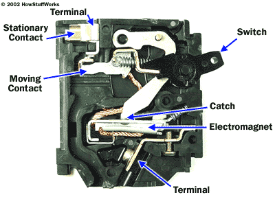
Like fuses, every circuit breaker has a specific ampere, voltage, and fault current interruption rating. The ampere rating is the maximum continuous current a circuit breaker can carry without exceeding its rating. As a general rule, the circuit breaker ampere rating should match the conductor ampere rating.
Generally the ampere rating of a circuit breaker is selected at 125% of the continuous load current. This usually corresponds to the conductor ampacity which is also selected at 125% of continuous load current. For example, a 125 ampere circuit breaker would be selected for a load of 100 amperes.
The voltage rating of the circuit breaker must be at least equal to the circuit voltage. The voltage rating of a circuit breaker can be higher than the circuit voltage, but never lower.
Circuit breakers are also rated according to the level of fault current they can interrupt. When applying a circuit breaker, one must be selected which can sustain the largest potential short circuit current which can occur in the selected application.
Saturday, June 13, 2015
Electrical Power Circuit Protection
Circuit protection must be taken into consideration with any electrical circuit, including busway. Current flow in a conductor always generates a watts loss in the form of heat. As current flow increases, the conductor must be sized appropriately in order to compensate for higher watt losses. Excess heat is damaging to electrical components. For that reason, conductors have a rated continuous current carrying capacity or ampacity.Overcurrent protection devices are used to protect conductors from excessive current flow. Two devices used to protect circuits from overcurrent are fuses and circuit breakers. These protective devices are designed to limit the flow of current in a circuit to a safe level, preventing the circuit conductors from overheating.
overcurrent is any current in excess of the rated current of equipment or the ampacity of a conductor. It may result from overload, short circuit, or ground fault.
Circuit protection would be unnecessary if overloads and short circuits could be eliminated. Unfortunately, overloads and short circuits do occur. To protect a circuit against these currents, a protective device must determine when a fault condition develops and automatically disconnect the electrical equipment from the voltage source.
An overcurrent protection device must be able to recognize the difference between overcurrents and short circuits and respond in the proper way. Protection devices use an inverse time-current characteristic. Slight overcurrents can be allowed to continue for some period of time, but as the current magnitude increases, the protection device must open faster. Short circuits must be interrupted instantly.
A fuse is the simplest device for interrupting a circuit experiencing an overload or a short circuit. A typical fuse, like the one shown below, consists of an element electrically connected to end blades or ferrules. The element provides a current path through the fuse. The element is enclosed in a tube and surrounded by a filler material.
Current flowing through the element generates heat, which is absorbed by the filler material. When an overcurrent occurs temperature in the element rises. In the event of a harmless transient overload condition the excess heat is absorbed by the filler material. If a sustained overload occurs the heat will eventually melt open an element segment forming a gap; thus stopping the flow of current.
Short-circuit current can be several thousand amperes and generates extreme heat. When a short circuit occurs several element segments can melt simultaneously, which helps remove the load from the source voltage quickly. Short-circuit current is typically cut off in less than half a cycle, before it can reach its full value.
Nontime-delay fuses provide excellent short circuit protection. Short-term overloads, such as motor starting current, may cause nuisance openings of nontime-delay fuses. They are best used in circuits not subject to large transient surge currents. Nontime-delay fuses usually hold 500% of their rating for approximately one-fourth second, after which the current carrying element melts. This means that these fuses should not be used in motor circuits which often have inrush (starting) currents greater than 500%.
Time-delay fuses provide overload and short circuit protection. Time-delay fuses usually allow five times the rated current for up to ten seconds. This is normally sufficient time to allow a motor to start without nuisance opening of the fuse unless an overload persists.
Fuses have a specific ampere rating, which is the continuous current carrying capability of a fuse. The ampere rating of a fuse, in general, should not exceed the current carrying capacity of the circuit. For example, if a conductor is rated for 10 amperes, the largest fuse that would be selected is 10 amperes.
There are some specific circumstances when the ampere rating is permitted to be greater than the current carrying capacity of the circuit. For example, motor and welder circuits can exceed conductor ampacity to allow for inrush currents and duty cycles.
The voltage rating of a fuse must be at least equal to the circuit voltage. The voltage rating of a fuse can be higher than the circuit voltage, but never lower. A 600 volt fuse, for example, can be used in a 480 volt circuit. A 250 volt fuse could not be used in a 480 volt circuit.
Fuses are also rated according to the level of fault current they can interrupt. This is referred to as ampere interrupting capacity (AIC). When applying a fuse, one must be selected which can sustain the largest potential short circuit current which can occur in the selected application. The fuse could rupture, causing extensive damage, if the fault current exceeds the fuse interrupting rating.
overcurrent is any current in excess of the rated current of equipment or the ampacity of a conductor. It may result from overload, short circuit, or ground fault.
Circuit protection would be unnecessary if overloads and short circuits could be eliminated. Unfortunately, overloads and short circuits do occur. To protect a circuit against these currents, a protective device must determine when a fault condition develops and automatically disconnect the electrical equipment from the voltage source.
An overcurrent protection device must be able to recognize the difference between overcurrents and short circuits and respond in the proper way. Protection devices use an inverse time-current characteristic. Slight overcurrents can be allowed to continue for some period of time, but as the current magnitude increases, the protection device must open faster. Short circuits must be interrupted instantly.
A fuse is the simplest device for interrupting a circuit experiencing an overload or a short circuit. A typical fuse, like the one shown below, consists of an element electrically connected to end blades or ferrules. The element provides a current path through the fuse. The element is enclosed in a tube and surrounded by a filler material.
Current flowing through the element generates heat, which is absorbed by the filler material. When an overcurrent occurs temperature in the element rises. In the event of a harmless transient overload condition the excess heat is absorbed by the filler material. If a sustained overload occurs the heat will eventually melt open an element segment forming a gap; thus stopping the flow of current.
Short-circuit current can be several thousand amperes and generates extreme heat. When a short circuit occurs several element segments can melt simultaneously, which helps remove the load from the source voltage quickly. Short-circuit current is typically cut off in less than half a cycle, before it can reach its full value.
Nontime-delay fuses provide excellent short circuit protection. Short-term overloads, such as motor starting current, may cause nuisance openings of nontime-delay fuses. They are best used in circuits not subject to large transient surge currents. Nontime-delay fuses usually hold 500% of their rating for approximately one-fourth second, after which the current carrying element melts. This means that these fuses should not be used in motor circuits which often have inrush (starting) currents greater than 500%.
Time-delay fuses provide overload and short circuit protection. Time-delay fuses usually allow five times the rated current for up to ten seconds. This is normally sufficient time to allow a motor to start without nuisance opening of the fuse unless an overload persists.
Fuses have a specific ampere rating, which is the continuous current carrying capability of a fuse. The ampere rating of a fuse, in general, should not exceed the current carrying capacity of the circuit. For example, if a conductor is rated for 10 amperes, the largest fuse that would be selected is 10 amperes.
There are some specific circumstances when the ampere rating is permitted to be greater than the current carrying capacity of the circuit. For example, motor and welder circuits can exceed conductor ampacity to allow for inrush currents and duty cycles.
The voltage rating of a fuse must be at least equal to the circuit voltage. The voltage rating of a fuse can be higher than the circuit voltage, but never lower. A 600 volt fuse, for example, can be used in a 480 volt circuit. A 250 volt fuse could not be used in a 480 volt circuit.
Fuses are also rated according to the level of fault current they can interrupt. This is referred to as ampere interrupting capacity (AIC). When applying a fuse, one must be selected which can sustain the largest potential short circuit current which can occur in the selected application. The fuse could rupture, causing extensive damage, if the fault current exceeds the fuse interrupting rating.
Distribution Systems
A distribution system is a system that distributes electrical power throughout a building. Distribution systems are used in every residential, commercial, and industrial building.

Distribution systems used in commercial and industrial locations are complex. A distribution system consists of metering devices to measure power consumption, main and branch disconnects, protective devices, switching devices to start and stop power flow, conductors, and transformers. Power may be distributed through various switchboards, transformers, and panel boards. Good distribution systems don’t just happen. Careful engineering is required so that the distribution system safely and efficiently supplies adequate electric service to both present and possible future loads.
A feeder is a set of conductors that originate at a main distribution center and supplies one or more secondary, or one or more branch circuit distribution centers.
Commercial and industrial distribution systems use several methods to transport electrical energy. These methods may include heavy conductors run in trays or conduit. Once installed, cable and conduit assemblies are difficult to change. Power may also be distributed using bus bars in an enclosure. This is referred to as busway.

Distribution systems used in commercial and industrial locations are complex. A distribution system consists of metering devices to measure power consumption, main and branch disconnects, protective devices, switching devices to start and stop power flow, conductors, and transformers. Power may be distributed through various switchboards, transformers, and panel boards. Good distribution systems don’t just happen. Careful engineering is required so that the distribution system safely and efficiently supplies adequate electric service to both present and possible future loads.
A feeder is a set of conductors that originate at a main distribution center and supplies one or more secondary, or one or more branch circuit distribution centers.
Commercial and industrial distribution systems use several methods to transport electrical energy. These methods may include heavy conductors run in trays or conduit. Once installed, cable and conduit assemblies are difficult to change. Power may also be distributed using bus bars in an enclosure. This is referred to as busway.
Subscribe to:
Posts (Atom)